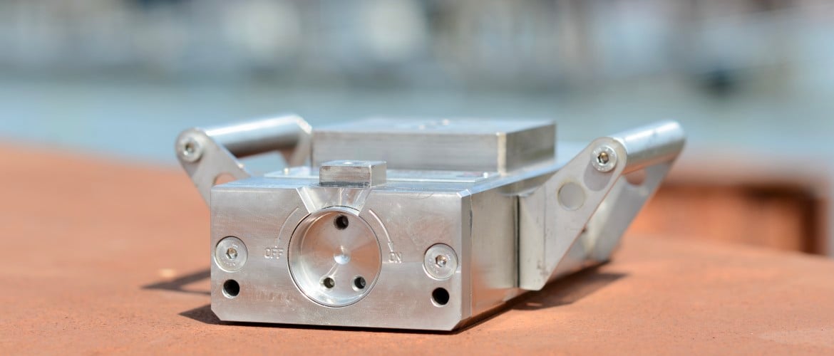
The subject of this blog is the capacity of the Controlock® magnet and the external influencing factors.
Magnets are widely known and used by us as individuals in our daily lives and by companies in the industry. As an example, you can think of the small and nicely designed and coloured magnets on our fridge to hold our photos and shopping lists or the gigantic magnets used in scrap yards and massive MRI machines.
Perhaps knowing the capacity of our fridge magnet is not that necessary, but it is essential to determine the actual force when it comes to industrial magnets. Knowing the exact strengths of the magnet is crucial because, in some cases, people’s lives depend on it.
The first question I always get when explaining the Controlock® concept is
“What is the capacity of Controlock® magnet?”
The capacity of the magnet depends on many factors. Therefore, this blog is designated to explain the correlation between the magnet force and external influences.
In this blog, you will read about the following topics:
- Weight/force ratio
- Size of the contact surface
- Influencing factors
- Air gap
- The thickness of the steel plate
- Type of steel
- Temperature
- Conclusion
Weight/force ratio
As a general rule, both switchable permanent magnet and electro-permanent magnet have 100 kilograms of breakout force per kilogram of their own weight. In other words, the load capacity of 1 kilogram of a magnet is 100 kilograms maximum under ideal circumstances.
Please note that, depending on the design of the magnet, the force can be higher (Neo 150: 2.8 kgs and 450 kgf breakaway force = 161 kgf/kg, scaffolding anchor: 2400 kgf at 18 kg weight = 133 kgf/kg) or lower for other types of magnets.
Size of the contact surface
Of course, the pole surface of the magnet must be fully covered and with thinner materials, in particular. And there must be a sufficient steel surface around the magnet to generate the required force.
To clarify, in order to place the Controlock® magnet in the right place, you must consider the following rule
Rule of thumb for 3- pole Controlock® scaffold anchor magnet:
(length of the magnet + width of the magnet) x (2x the width of the magnet)
(300 mm + 120 mm) x (120 mm +120 mm)
= 420 x 240 mm
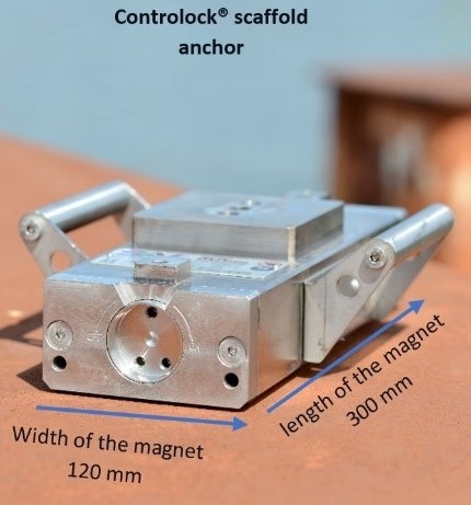
The rule mentioned above applies to the Controlock® scaffold anchor.
Close to the edge of an object, the force will be less than in the middle. The impact of this will be higher with thinner steel.
Influencing factors
You might wonder
“Why does the capacity of each magnet differ even though the magnets are exactly the same?”
Indeed, the Controlock® magnets are the same. However, sometimes there are some slight variation in the magnetic material used, and manufacturing tolerances give variation in the force.
Another aspect is the counter surface, on which the magnet is mounted, is always different. There are many factors to consider when we talk about magnet capacity. Depending on the factors that influence the magnetic force, some magnets have a load capacity of 139 kilograms per kilogram of weight.
The factors influencing the force are the air gap, the thickness of the steel plate, the type of steel, and temperature.
Air gap
The air gap occurs typically between the steel wall and the anchor—the more significant the air gap, the lower the force. Due to the strong influence of air gaps, the operator must control every magnet for the actual force on the location. An air gap can be created by, e.g., paint, dirt, roughness, unevenness, or rust between magnet and wall. The manual describes the tests and the necessary test equipment.
The influence of the air gap size
Controlock® was tested to determine its strength in relation to an air gap. The presented values are based on a sheet (wall) thickness of 10 mm of soft, low-carbon steel (St37). 1 kgf equals 1 daN. The forces are lower when thinner steel sheets/walls are used.
In this blog, I intentionally use the term pull force; the official term in mechanics is “normal force.”
The results were as follows.
| Air gap in mm | Pull force in kgf | Shear force in kgf |
| 0 | 1400 | 545 |
| 0.5 | 1100 | 440 |
| 1 | 800 | 310 |
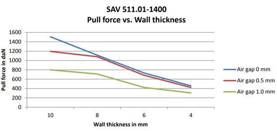
Even small air gaps like 0,5 mm or 1 mm may reduce the magnetic force enormously from 15 kN at 0 mm air gap to 8 kN at a 1 mm air gap. The effects of wall thickness and air gap demonstrated in the graph below are valid for one type of magnets. Other types of magnets will show different dependencies.
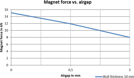
The thickness of the steel plate
The magnet achieves its designed force when the material is 10 mm thick—the strength will decrease with
| Thinner material Uneven surface | Corrosion Fouling | Paint layers |
Controlock® was tested to determine its strength in relation to a steel wall; see the graph below. By reducing the thickness of the metal counterface from 10 mm to 4 mm, the magnetic force reduces from 15 kN to 4,5 kN. The effects of wall thickness and air gap presented in the graph below are valid for one type of magnets. Other magnets will show different dependencies.
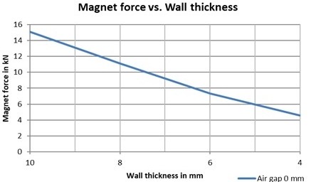
The graph below illustrates the correlation between the air gap size and the wall thickness in regard to the Controlock® pull force.
Type of steel
The pull force is based on low-alloy, low-carbon steel, e.g., S 235JR (St 37). Higher carbon content and more alloying will result in a lower force. In other words, most mechanically worthless steel is magnetically the best. Every material surcharge lowers the holding power.
Temperature
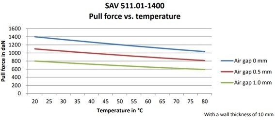
The designed force is achieved at a temperature of 20°C. At higher temperatures, the force reduces by just under 0.3% per degree. The maximum temperature is 80°C, which is equal to a force reduction of about 16%. The force is in daN. 1 daN = 1 kgf.
The graph below shows the influence of the air gap size and the temperature on the Controlock® pull force.
Conclusion
To conclude, the actual capacity of the magnet can differ widely depending on the external circumstances. The magnet’s force can increase or decrease depending on the air gap, steel surface size and type, and temperature. Consequently, testing the Controlock® magnet before declaring it ready for operation is mandatory.
The information about the testing steps and equipment are explained thoroughly in the manual.
For more information,
Please visit mcnetiq.com.
Send an email to info@mcnetiq.nl
Call us on +3185 130 2161
Or fill in the form below

